SACHS 505/2 A K S ... 505/2 D K
ZUSAMMENBAU DES MOTORS REBUILDING THE ENGINE
MONTAGE DU MOTEUR
Caution !
Gehäuse-Oberteil mit 2 Sechskantschrauben M Bx65
und Muttern an die Montage-Vorrichtung schrauben (siehe Bild 2).
Dichtflächen der Gehäuseteile mit Loctite 572 bestreichen, Dichtungsmasse nicht auf die Lagerstellen bringen.
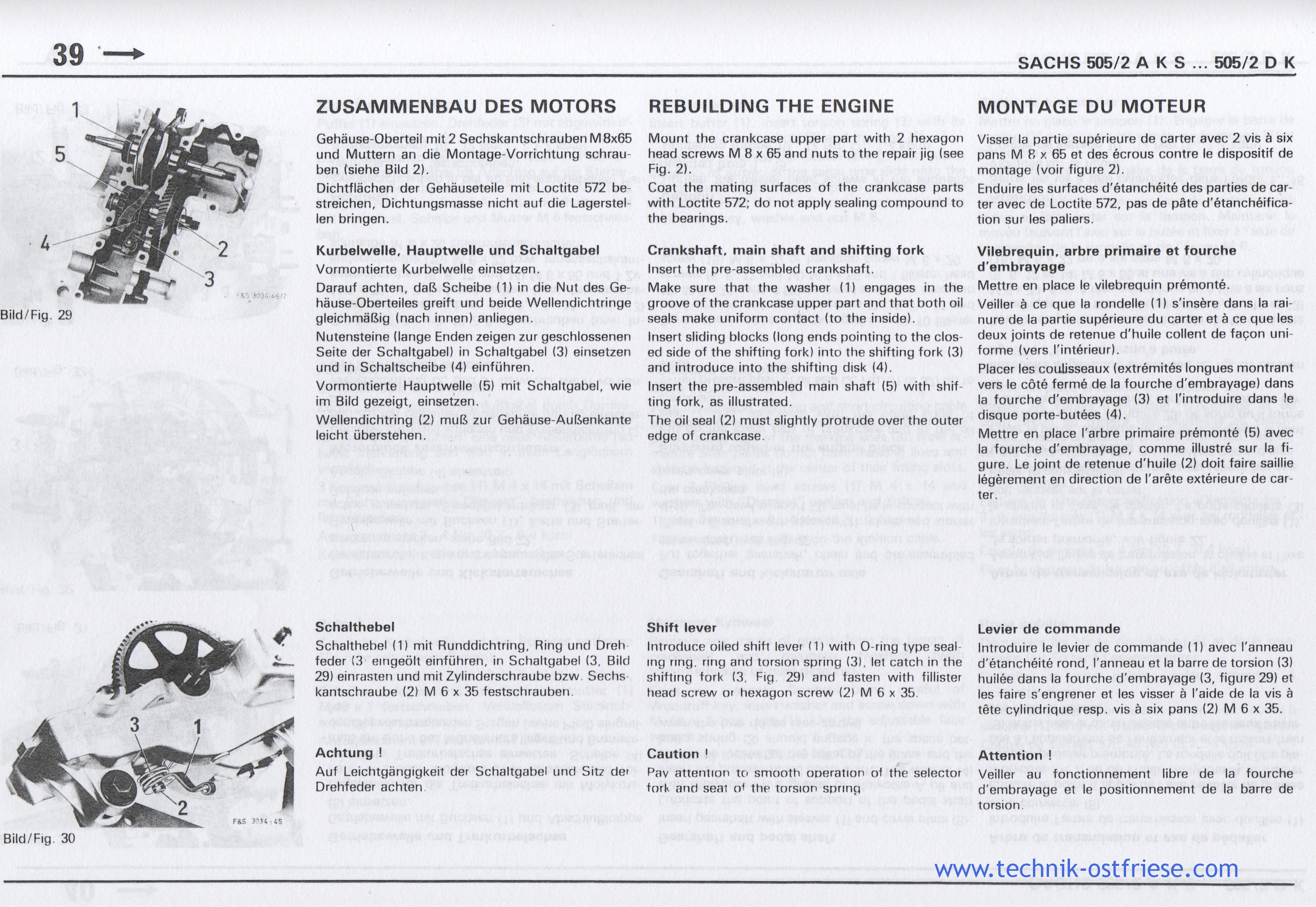
Kurbelwelle, Hauptwelle und Schaltgabel
Vormontierte Kurbelwelle einsetzen.
Darauf achten, daß Scheibe (1) in die Nut des Gehäuse-Oberteiles greift und beide Wellendichtringe
gleichmäSig (nach innen) anliegen.
Nutensteine (lange Enden zeigen zur geschlossenen
Seite der Schaltgabel) in Schaltgabel (3) einsetzen
und in Schaltscheibe (4) einführen.
Vormontierte Hauptwelle (5) mit Schaltgabel, wie
im Bild gezeigt, einsetzen.
Wellendichtring (2) muE zur Gehäuse-Außenkante
leicht überstehen.
Schalthebel
Schalthebel (1) mit Runddichtring, Ring und Drehfeder (3 eingeölt einführen, in Schaltgabel (3, Bild29) einrasten und mit Zylinderschraube bzw. Sechskantschraube (2) M 6 x 35 festschrauben.
Achtung !
Auf Leichtgängigkeit der Schaltgabel und Sitz der
Drehfeder achten.
Mount the crankcase upper part with 2 hexagon
head screws M 8 x 65 and nuts to the repair jig (see
Fig. 2).
Coat the mating surfaces of the crankcase parts
with Loctite 572; do not apply sealing compound to
the bearings.
Crankshaft, main shaft and shifting fork
Insert the pre-assembled crankshaft.
Make sure that the washer (1) engages in the
groove of the crankcase upper part and that both oil
seals make uniform contact (to the inside).
Insert sliding blocks (long ends pointing to the clos-
ed side of the shifting fork) into the shifting fork (3)
and introduce into the shifting disk (4).
Insert the pre-assembled main shaft (5) with shif-
ting fork, as illustrated.
The oil seal (2) must slightly protrude over the outer
edge of crankcase.
Shift lever
Introduce oiled shift lever (1) with O-ring type sealing ring, ring and torsion spring (3), let catch in the shifting fork (3, Fig 29) and fasten with fillister head screw or hexagon screw (2) M 6 x 35.
Pav attention to smooth operation of the selector
fork and seat of the torsion spnng
Visser la partie superieure de carter avec 2 vis a six
pans M 6 x 65 et des ecrous contre le dispositif de
montage (voir figure 2).
Enduire (es surfaces d'etancheite des parties de car-
ter avec de Loctite 572, pas de päte d'etancheifica-
tion sur (es paliers.
Vilebrequin, arbre primaire et fourche
d'embrayage
Mettre en place le vilebrequin premonte.
Veiller a ce que la rondelle (1) s'insere dans la rai-
nure de la partie superieure du carter et a ce que les
deux joints de retenue d'huile collent de facon uni-
forme (vers I'interieur).
Placer les coulisseaux (extremites longues montrant
vers le cote ferme de la fourche d'embrayage) dans
la fourche d'embrayage (3) et I'introduire dans le
disque porte-butees (4).
Mettre en place I'arbre primaire premonte (5) avec
la fourche d'embrayage, comme illustre sur la fi-
gure. Le joint de retenue d'huile (2) doit faire saillie
legerement en direction de I'arete exterieure de car-
ter.
Levier de commande
Introduire le levier de commande (1) avec I'anneau
d'etancheite rond, I'anneau et la barre de torsion (3)
huilee dans la fourche d'embrayage (3, figure 29) et
les faire s'engrener et les visser a I'aide de la vis a
tete cylindrique resp. vis a six pans (2) M 6 x 35.
Attention !
Veiller au fonctionnement libre de la fourche d'embrayage et le positionnement de la barre de torsion.